Week 2 Lab Project
Exploring CD players, resistor arrays, and optical potentiometers
September 30, 2009
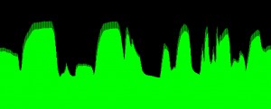
For this assignment, I started with the idea of building a crude "CD player" with a rotating cardboard disc, 3 pen lasers, 3 photocells and a modified version of the multiplexer I built for last week. Building from Tom Igoe's Graph code, I produced the following visualization of a single photocell test:
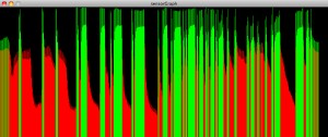
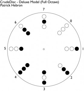
I wrote an ambient light normalization procedure in order to maximize the on/off effect (represented here by green/red respectively), which will act as a trigger for the software demultiplexer. The procedure is very simplistic and needs work. As of now, it uses the first 24 readings to find an average ambient level. Any subsequent reading which is greater than 1.1 times the average ambient level triggers the on state. I would like to maximize the viewer's ability to see the machinations and so casing the device in a black box is not an option. Here are the possible sensor states depicted on a sample "CD."
PART 2:
I've decided not to pursue the CD player for this assignment because there is too much overlap with my previous project and I'd like to explore some other possibilities. As a foundational variable resistor exercise, I built the following resistor array:
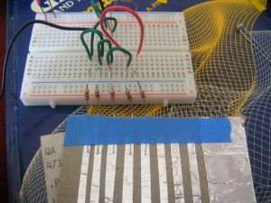
which yielded this graph:
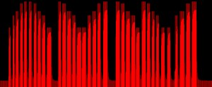
Naturally, a resistor array doesn't give you a fluid resistance transition like a potentiometer. But it provides a series of discrete values – 10K, 4.7k, 3.3k, 1k, 470 ohms, in the case of my demo model – to a single analog input on the Arduino and can therefore be used as one axis of a touchscreen-like device. The demo model requires a charged stylus. I'm looking into resistive and capacitive approaches to actual touchscreens, but so far my aluminum foil, wax paper and plastic wrap tests have yielded no results.
I also tried using a forcefully drawn graphite line on paper as a potentiometer-style variable resistor. This worked, but the resistance was extremely high even with an extremely short line and so it was difficult to gather usable results. I then tried a mechanical pencil lead, which was somewhat better but had too little resistance. A precise mixture is clearly the defining feature of a resistor. I also did some experiments with a flexible sensor.
But something was missing from my project… So far, with possible exception of a volume knob for the CD player, I had not come up with a device that made use of more than one sensor in a related way. At some point, I'd like to look at the gyro/accelerometer combo.
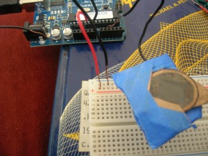
I just thought of a way to build an optical potentiometer using a photocell and two polarizing filters. Here are the components (from right):
- A photocell is encased behind a polarizing filter, which I cut from RealD stereoscopic glasses (a circular polarizing filter).
- Another polarizing filter is glued to a cardboard dial.
- An LED, which I initially thought would serve as a constant light source for the device. But after implementing a test model, I determined ambient light was sufficient for demonstration.
Here is the assembled demo model:
Here is a graph of the optical potentiometer's output:
It gives good, clear differentiation as the dial is turned. But the range is a bit narrow. Perhaps this could be improved by encasing an LED over the top filter rather than using ambient light. I'm gonna keep working, more later…